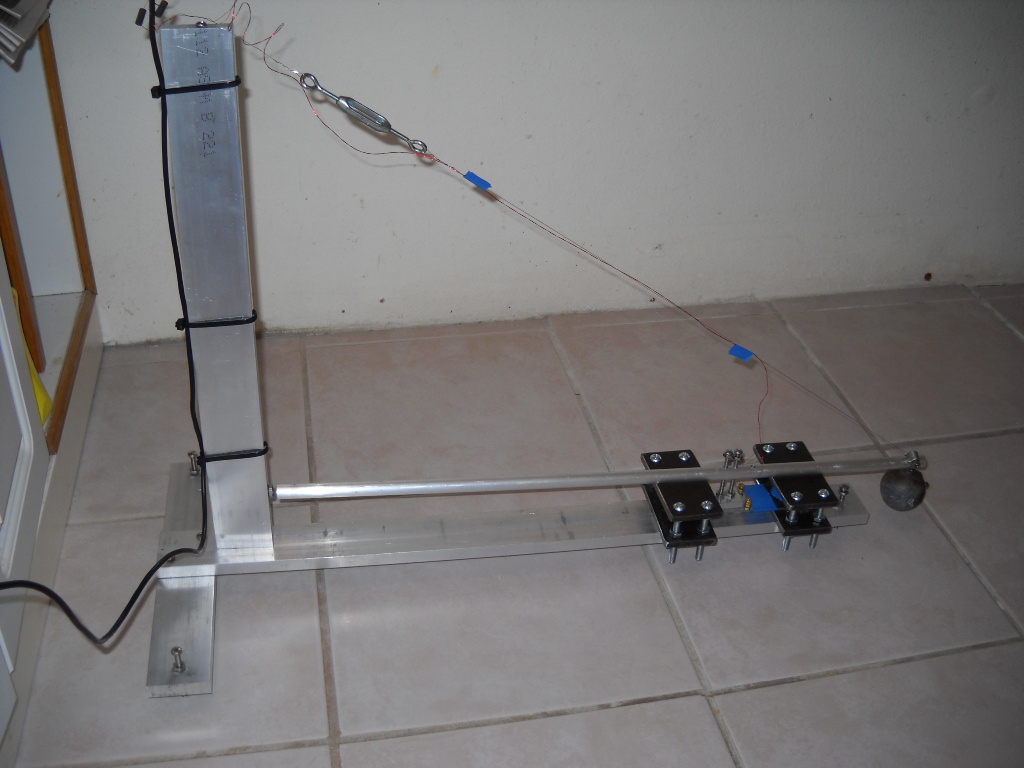
The seismometer installed on our first floor, which sits on a concrete slab.
A home-built Lehman Seismometer
Send comments or suggestions to: Ken, W7KKE.
For several years I've heard about individuals and schools having built seismometers. To me it was amazing that a home made seismometer could detect the faint tremors from thousands of miles away. In the summer of 2015 I started seriously searching the internet for information and finally found enough where I felt I had a chance of success.
The style I chose was a "Lehman Seismometer" sometimes referred to as a "garden gate" seismometer. It consists of a mass at the end of boom, some powerful magnets, a coil of wire, and some electronics to amplify and digitize the faint voltage generated when a tremor is received.
One concern I had before starting the project was my location,
which is only three blocks from the Pacific Ocean. I'd seen several
reports of the problems caused by crashing surf, but I decided to
proceed. In the summer, our surf is normally quite small, but during
the fall and winter storms we have seen 30 foot swells reported from
the weather buoys 20 miles offshore.
(Click on
images for larger size.)
The seismometer installed on our first floor, which sits on a
concrete slab.
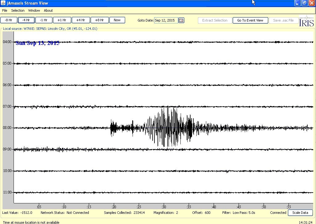
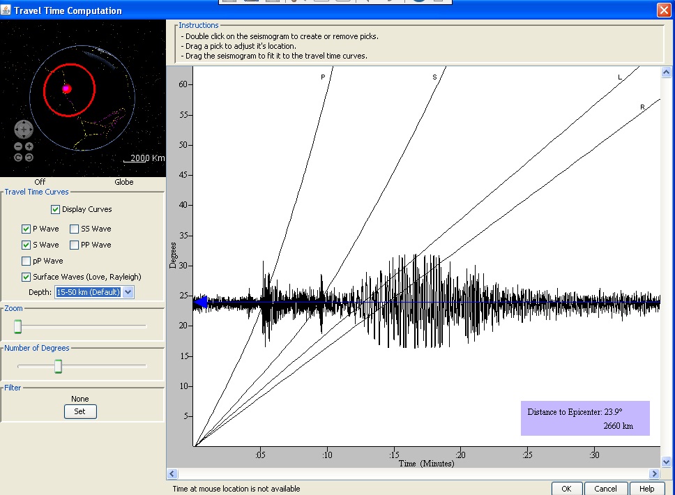
An 6.8 magnitude quake detected in the Gulf of California,
over 1600 miles from my home in Lincoln City, Oregon.
The software used to view the seismometer output is jAmaseis. It can be downloaded at: http://www.iris.edu/hq/jamaseis/
Besides viewing your own seismometer output, you can view activity from schools and professional seismometers.
Here's the jAmaseis timing analysis from the “Event View” of that Gulf of California quake:
Construction
It seemed like a good idea to first start with the electronics, then once I had that working, proceed to the metal work.
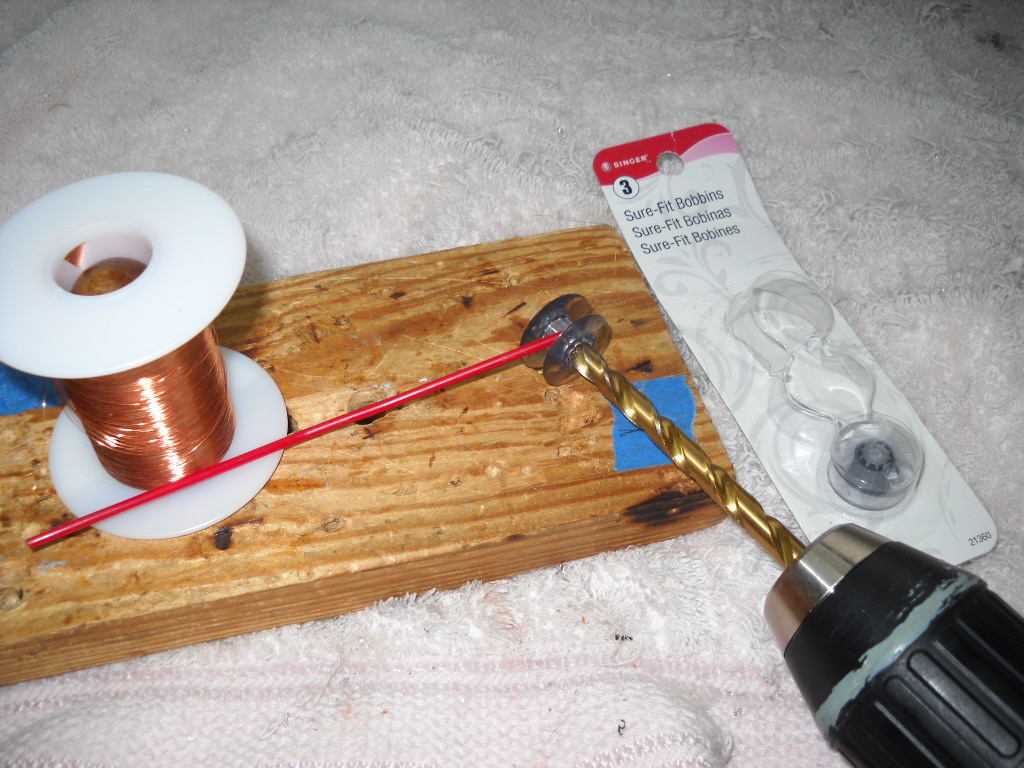
1. Winding the coil
At the local sewing and crafts store I found some sewing machine bobbins (“Sure-Fit Bobbins #3”) and filled one of them up with #34 wire. The red plastic tube is used to maneuver the wire while winding the bobbin. The instructions I found on the internet said to wind about 2000 turns. Since there was no way I was going to count that many turns I just filled the bobbin to the edge.
After winding, the coil measured approximately 240 Ohms and produced some voltage in the micro-volt range when wiggled over a strong magnet. This corresponds to approximately 1000 turns using 0.243 Ohms per turn for #38 wire. (The 0.243 Ohms value was determined from other web pages that listed the resistance for a given number of turns of this size wire.) Although the coil seems very sensitive, at some future date I may wind another using a larger bobbin.
Op-Amp, Filter, and A-D Converter
The Op-Amp amplifies the small voltages produced by the coil moving in the magnet and the filter removes some noise from the signal. The filtered signal is converted to digital by the Analog to Digital (A-D) Converter. I had an unused Arduino Uno laying around. It has several handy A-D inputs so I pressed that into service.
A circuit for the Op-Amp / Filter was found at: http://www.infiltec.com/seismo/inf-qmsd.gif Since I had the Arduino Uno, I did not include the PIC 14000 in my project. IMPORTANT NOTE: There are two capacitor values shown in the image that are hard to read. C2 and C4 are nanofarards, NOT microfarads!
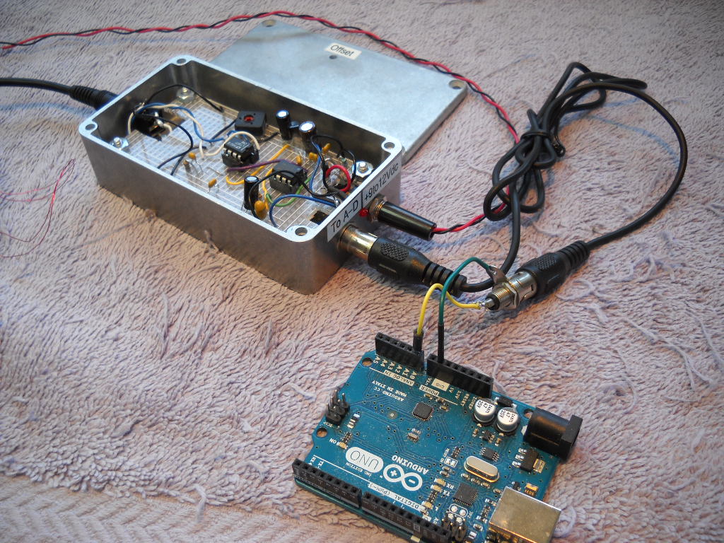
The Arduino A to D code simulates a SEP seismometer. The baud rate is 9600 and the output is ASCII text ranging from -32768 to +32,768. Each line is ended with a Line Feed character. Here's the Arduino sketch I'm using for this project: AtoD.ino.txt
At this point you can debug the coil, Op Amp, Filter, and A-D Converter. Either a terminal program such as HyperTerm or the jAmaseis program can be used to check the output.
Magnet Assemblies
There are two magnet assemblies used – one for the damping magnets and the other for the coil. Here's the instructions posted by Chris Chapman: http://jclahr.com/science/psn/chapman/lehman/index.html
Here's a view of my magnet housings before installing the magnets.
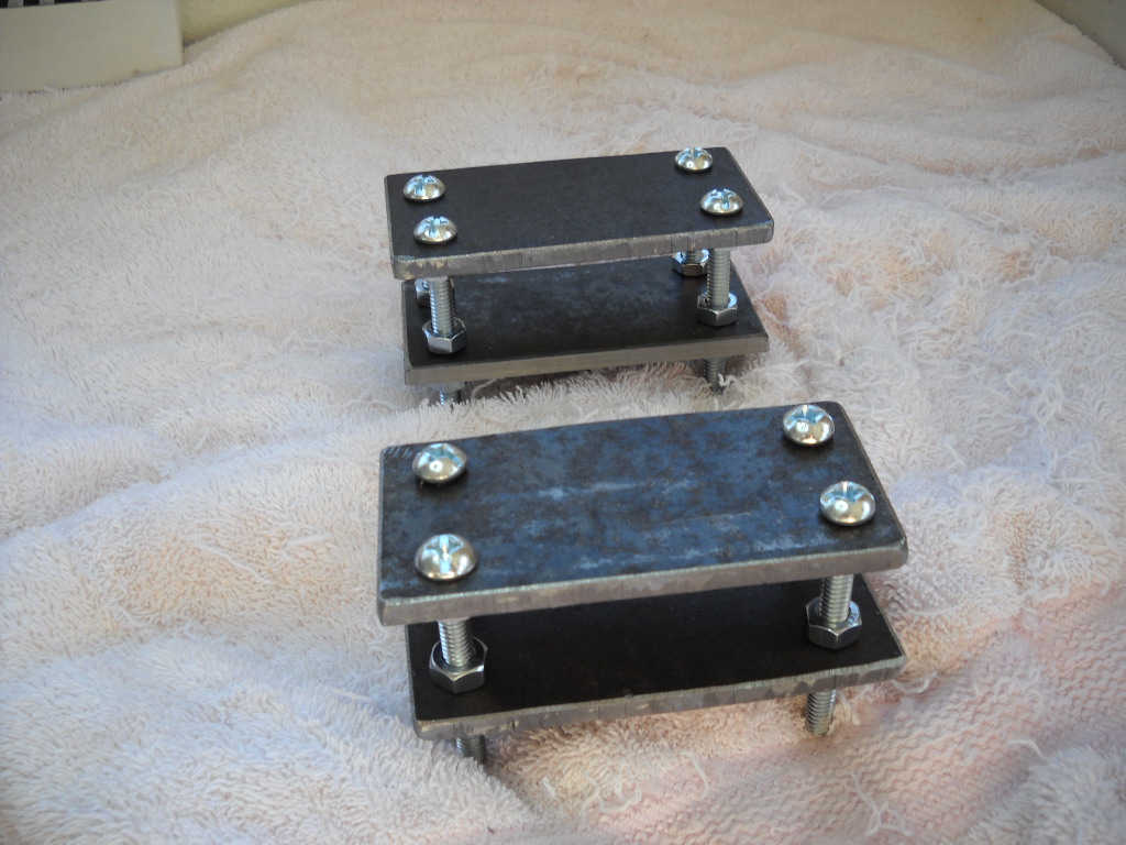
I used a saber saw to cut the ¼ inch mild steel. A better alternative would have been to order the steel cut to size from http://www.onlinemetals.com/ as I did with the aluminum bar stock later in the project.
The Neodymium magnets were ordered from “Amazing Magnets”: http://www.amazingmagnets.com/sf-plate-magnets.aspx?gclid=CNzU872q98cCFdgUgQodk7AHgA
My bill of materials for the magnets:
Neodymium Square Magnet, 1 inch x 1 inch, 1/8” thick (quantity 4) (for the damping magnet assembly)
Neodymium Plate Magnet, 1” x 1/2”, 1/4” thick (quantity 4) (for the sensor magnet assembly)
Assembling the frame
The 2 inch by half inch aluminum bar stock was ordered cut to length from http://www.onlinemetals.com/ . After looking at the various types of aluminum available, I chose the 6061-T6511. The pendulum is two feet of half inch aluminum rod which is a stock item. The frame is drilled and tapped to accept 10-32 screws. Holes were also drilled and tapped for the 8-32 adjustment screws.
My bill of materials for the frame and boom:
(All 6061-T6511 Aluminum)
0.5” x 2” Extruded Aluminum Rectangle cut to 26 inches (the long bottom support)
0.5” x 2” Extruded Aluminum Rectangle cut to 16 inches (the vertical support)
0.5” x 2” Extruded Aluminum Rectangle cut to 12 inches (the horizontal support)
0.5” Extruded Aluminum Round 24 inch standard stock (the pendulum boom)
Here's what the assembled frame and pendulum boom looks like. The magnet housings sit on the frame. The weight at the end of the pendulum is a 1 pound lead fishing weight attached using a small stainless hose clamp. The hose clamp is attached to the weight with a small stainless screw. The small support wire is a 0.30 mm guitar string.
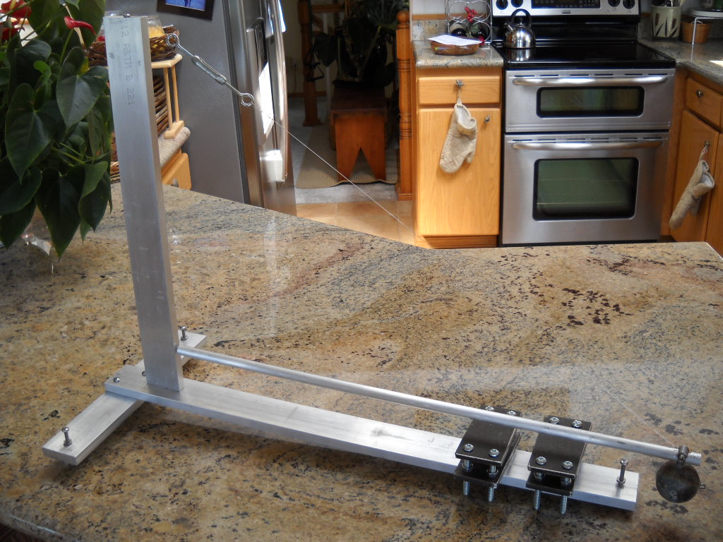
At this point you can check the pendulum's natural period. Ideally, according to other construction pages, the period should be about 20 seconds. I was able to achieve 15 to 17 seconds with my temporary pivot. Note: At this point the coil and damping assemblies have not been installed.
Except for the magnet housings and their bolts, all the material was non-ferrous.
Boom Pivot
The pivot is very important for proper operation. To get something running temporarily I drilled a small hole in the end of the boom and inserted a steel pin salvaged from a map tack. This sat in a small dimple I drilled into the vertical support. Here's what the first pivot looked like:
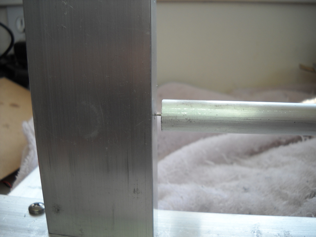
Obviously this was only temporary but using this pivot, the seismometer did detect a magnitude 6.4 quake in New Zealand, but it was just barely discernible on the jAmaseis display.
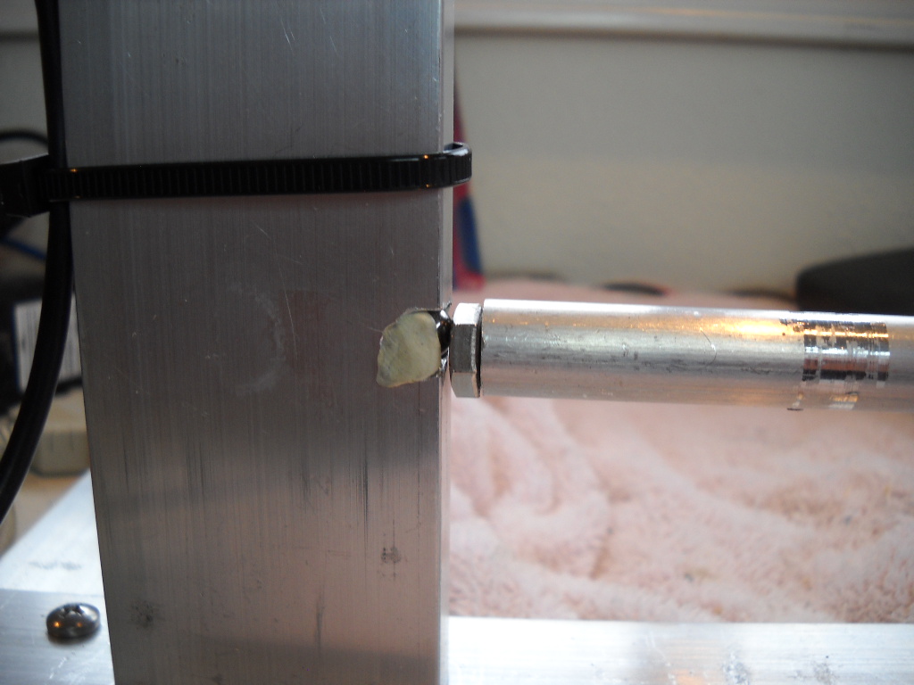
A second pivot was constructed which used the same steel pin, but this time resting in a dimple in a stainless steel bolt head.
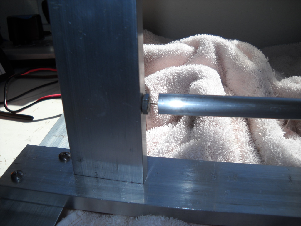
This pivot seems to perform better and the image of the quake at the top of this page was when the seismometer was using this pivot.
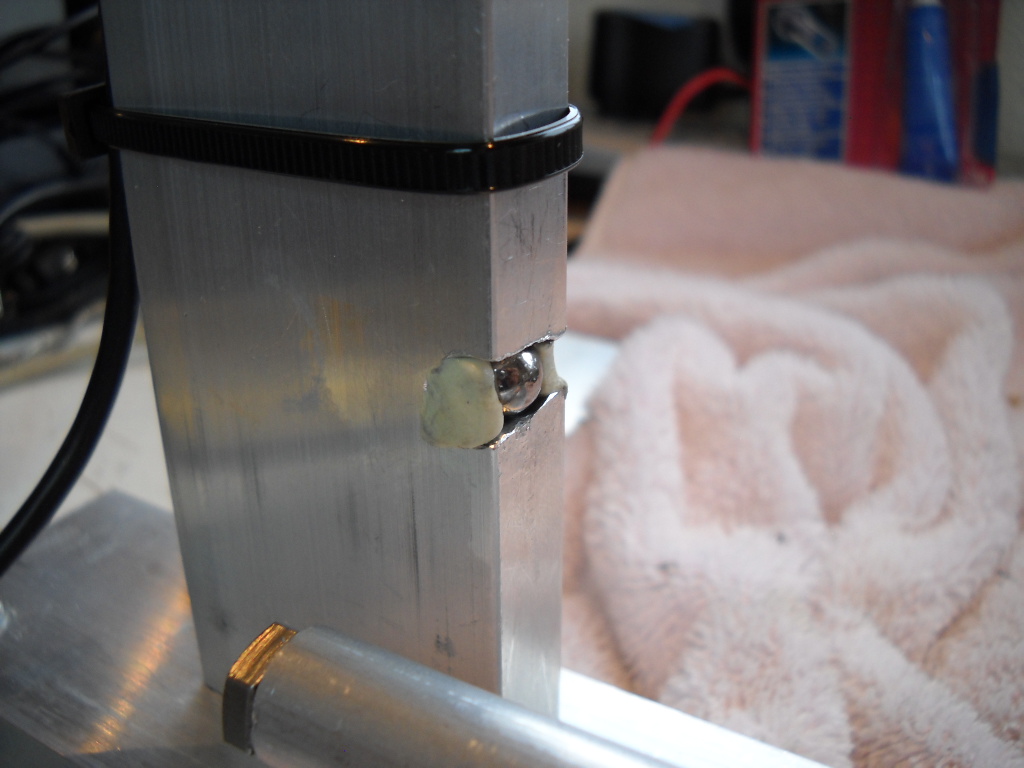
Finally, I assembled a ball bearing pivot. The ball bearing is stationary and the polished bolt head rotates over the ball bearing. This pivot performs very well.
Sensor and Damping Assemblies
The sensor coil was attached to a .080” plastic sheet using hot glue. Brass screws were used to attach the very small sensor wires to somewhat larger wires that were fed up the support wire to the top of the support member. A 1/4” thick piece of aluminum was used for the damping assembly. Both the sensor and damping magnet housings can be slid along the bottom support as required. The two long screws are stainless and are used to adjust the sensor and damping paddles so they move freely within the magnet housings.

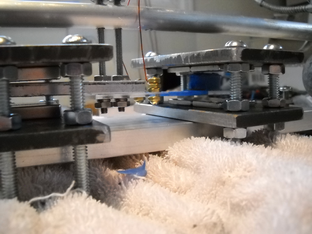
A closer view of the sensor and damping bar floating within the magnet housings:
Installation
Here's what the unit looks like when installed. The three adjustment screws rest on the tile floor which is sitting on a concrete slab. A turnbuckle, which could be smaller, is used to adjust the boom height. The assembly sits slightly tilted to the right and the right hand adjustment screw is used to fine-tune the pendulum period. The two adjustment screws on the cross member is used to center the pendulum over the magnet assemblies.
So far, traffic on our street doesn't affect the seismometer. Daily moving about the house occasionally causes a wiggle but door slams, and foot steps near the seismometer are readily identifiable on jAmaseis. At some point I'll build a cover to keep drafts from the sensor, although it's in a pretty protected spot under the stairs.
A small twisted pair of enamaled wires are run from the sensor coil to the top of the vertical support. There it is attached to a shielded pair of wires (the black cable) leading to the Op Amp / Filter input. I kept quite a bit of coiled slack at the top of the vertical support to avoid impacting the pendulum's swing.
References:
Here are links to the web pages I found useful during construction (some are repeat of links included earlier):
Good info on the different types of seismic waves: http://www.geo.mtu.edu/UPSeis/waves.html
jAmaseis software: http://www.iris.edu/hq/jamaseis/
The original 1979 Scientific American article describing the Lehman Seismometer: http://www.seismicnet.com/lehmntxt.html
Chris Chapman's great web page: http://jclahr.com/science/psn/chapman/lehman/index.html
Another web page on a home-built seismometer. Good info on the magnet assemblies: https://sites.google.com/site/seismicsensorinfo/lehman-seismometer
Infiltec's page. They sell assembled Op-Amp / A-D boards, as well as generously providing construction details: http://www.infiltec.com/seismo/
A page describing geophones as well as seismometer construction. Has some pictures of his ball bearing pivot: http://www.sydneystormcity.com/g_phones.htm
This page describes seismometer pivot assemblies: http://www.myeclectic.info/SeismoPivots/seismopivots.htm
An old, but still useful, page on Lehman Seismometer construction: http://ed-thelen.org/Seismo/Seismo.html
Mindsets in the UK sells USB interfaces in case you don't want to build your own: http://www.mindsetsonline.com/Catalogue/ProductDetail/seismometer-interface-usb-?productID=b1618034-53f4-48e3-b7c0-fdc72177990f&catalogueLevelItemID=eb895868-30f0-4af2-99fb-f0013e1937e1