|
|
||||||
Antennas |
||
|
The following links and files contain information for various antennas. |
|
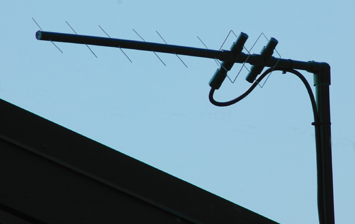
916.5 MHz Receiving Antenna for Wireless Weather Stations |
|
The 916.5 MHz receiving antenna for wireless weather stations is used to improve the reception of remotely located weather sensing units. The antenna is built on a PVC schedule 40 boom using copper wire elements cut from #14 copper house wire. The insulation is stripped off of the copper wire elements. Element lengths and spacings are shown in the following picture/diagrams: |
| 916.5 MHz Antenna |
Design/build information for the 916.5 MHz Receiving Antenna. |
|
| Quagi_916MHz_Rev2.zip |
Design file for the 916.5 MHz Receiving Antenna. |
|
Miscellaneous Functions |
||
|
The following links and files contain information for miscellaneous functions. |
|
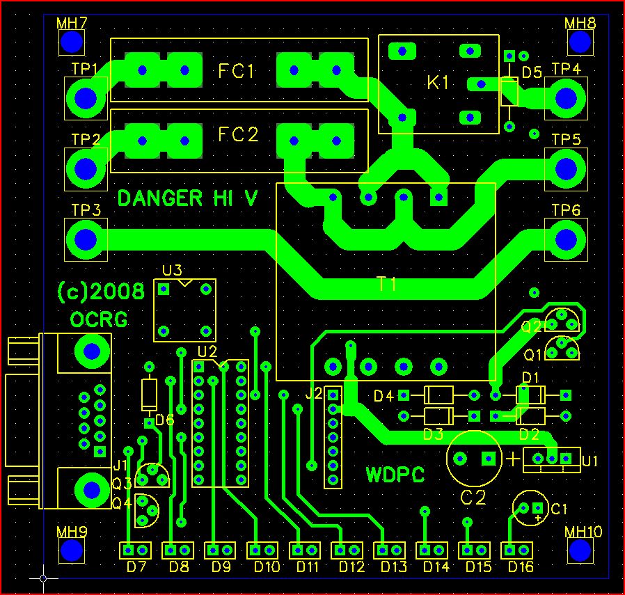
Watchdog Power Cycler |
|
The WDPC - Watchdog Power Cycler is an activity monitor for remote sites. Upon the loss of a heartbeat signal, the WDPC will produce a power down/power up cycle and wait for the remote equipment to reboot and then again start looking for the "I'm Alive" heartbeat signal. If the signal is again not present the power cycle will be repeated until the "I'm Alive" heartbeat returns. |
| WDPC.zip |
Design files for the Watchdog Power Cycler. Includes schematics, micro-controller firmware source code, firmware hex image file, photos and mechanical details. |
|
Packet Radio Telemetry |
||
|
The following links and files contain information for packet radio telemetry. |
|
KPC Telemetry |
|
Sending remote site telemetry data using the KPC TNC. |
| KPC-3+_Telemetry.pdf |
KPC-3+ Telemetry Input and Control Output Standardization Document for Oregon Coast Repeater Group APRS Digi-peaters and Network Nodes. |
|
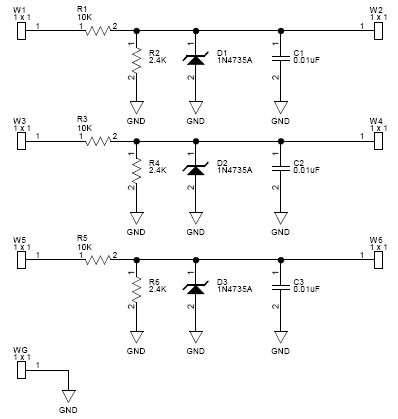
| KPC_Telemetry.zip |
Design files for a KPC TNC Telemetry Adapter and Monitored Voltage Signal Attenuator. Includes schematics, PCB layout, and photos. |
|
|
Telemetry Monitor |
|
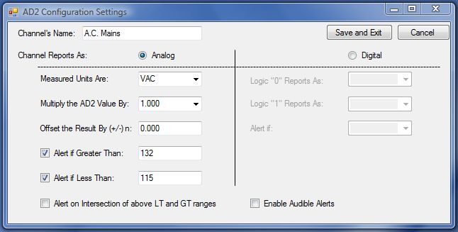
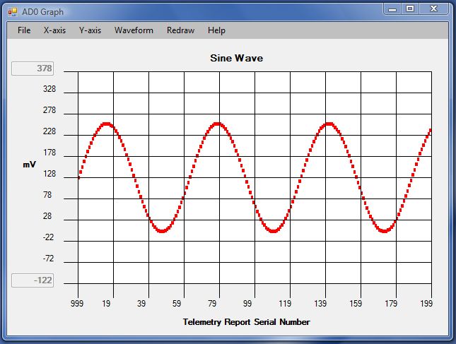
The Telemetry Monitor is a PC program for monitoring KPC-3+ TNC telemetry data
or any telemetry data that is received in the KPC-3+ telemetry format. The Telemetry
Monitor program shows all telemetry channels on the main screen and generates
graphical plot screens for each individual channel.
|
| TelemetryMonitor.zip |
Zip file contains TelemetryMonitor.exe, SampleTelemetry.txt and METER.ICO. |
|
Radios |
||
|
The following links and files contain information for various radio upgrades. |
|
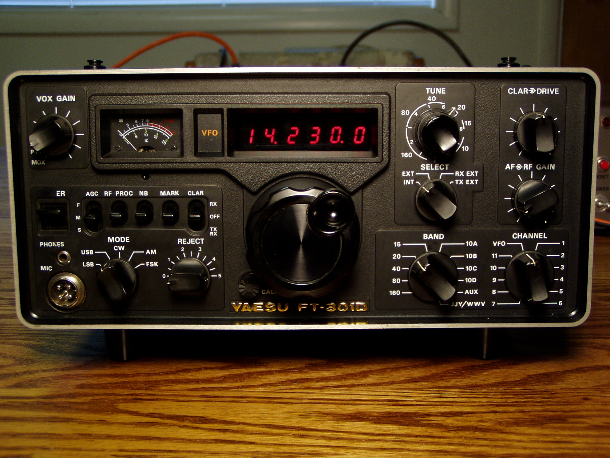
Yaesu FT-301D Replacement Display Yaesu FT-301D Replacement Display Document |
|
The Yaesu FT-301D transceiver's digital readout display used TIL-306 and TIL-308 LED display devices that have long gone obsolete. Those display devices ran hotter than blazes and frequently failed due to a lack of cooling. This paper and accompanying files (see below) contain the documentation for a new, directly plug in compatible, digital display for the Yaesu FT-301D transceiver. |
|
!!! Updated !!! FT301D_Replacement_Display_A03.zip !!! Updated Firmware !!! !!! Build Hints !!! |
Nov. 30, 2012: Includes firmware update A03 that displays dashes in the display when an unpopulated crystal channel is selected, or if an external VFO is selected and it is not powered on or it is not attached. Also shows a fixed "5.000.0" value for the JJY/WWV switch position. This firmware update is compatible with all circuit board versions of the "FT-301D Replacement Display."
Dec. 6, 2012:
Aug. 12, 2013:
Aug. 15, 2013: Sep. 5, 2013: Firmware Rev. A04. This firmware release adds two new important features to the FT-301D Replacment Display. The new features include the ability for the user to set and save the display's brightness level and the ability for the user to set and save the display's resolution. The display resolution can be set to operate as: 10Hz mode: Shows 10 Hz for all bands by eliminating the MHz digit(s). 100Hz mode: Shows 100 Hz for all bands; like the original Yaesu display. Floating Hz mode: Shows 10 Hz for 160m, 80m, 40m. Shows 100Hz for 20m, 15m, 10m. Click HERE for a description on how to use these new features. This firmware update is compatible with all circuit board versions of the "FT-301D Replacement Display." A big THANK YOU to Carlos Levy, PY1EGG, for his suggestion of these new feature additions and for his testing and feedback of the resulting implementation.
- - - - - - - - - - - - - - - - - - - - |
|
Radio Accessories |
||
|
The following links and files contain information for various radio accessories. |
|
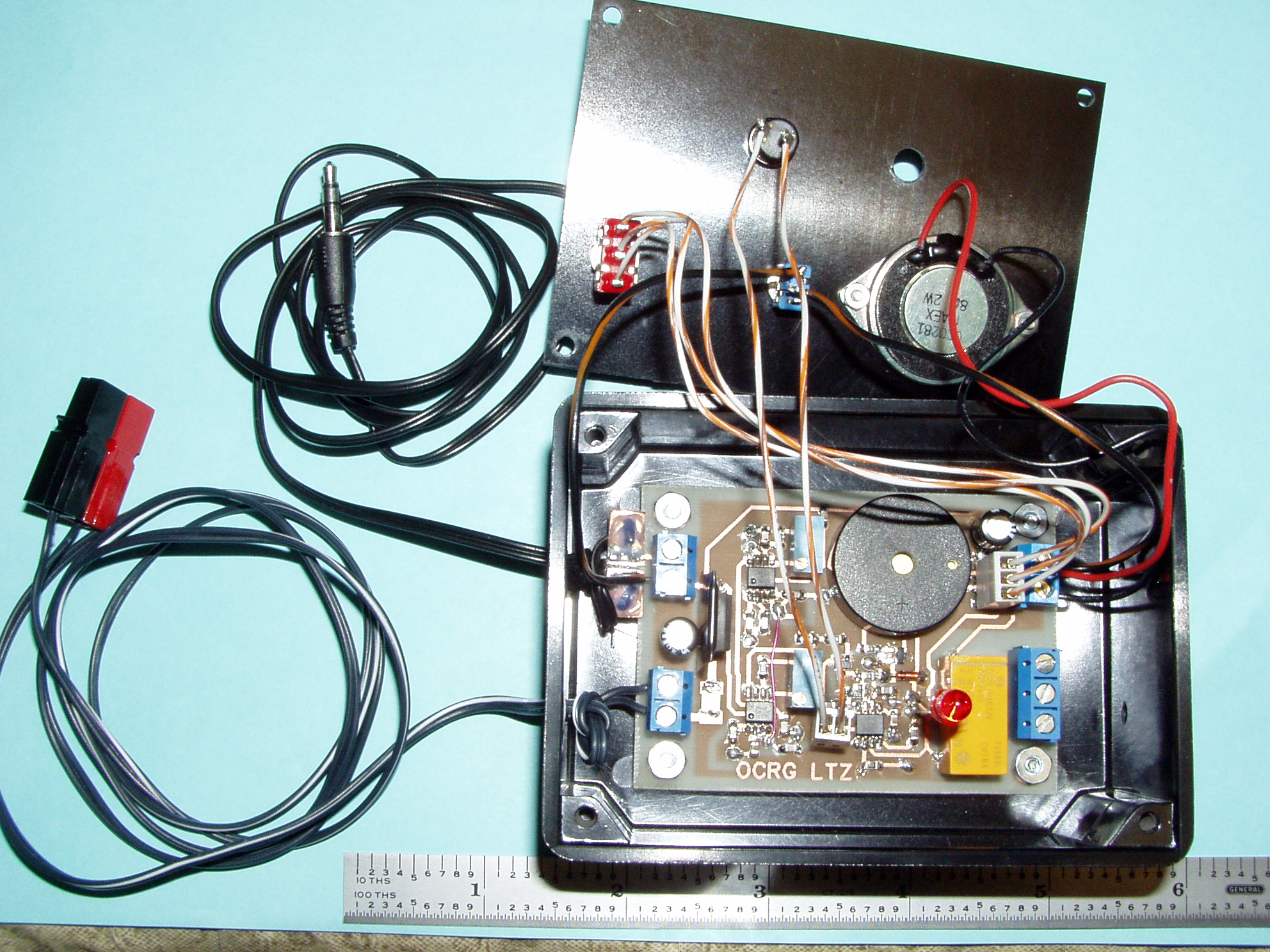
Long Tone Zero Decoder |
|
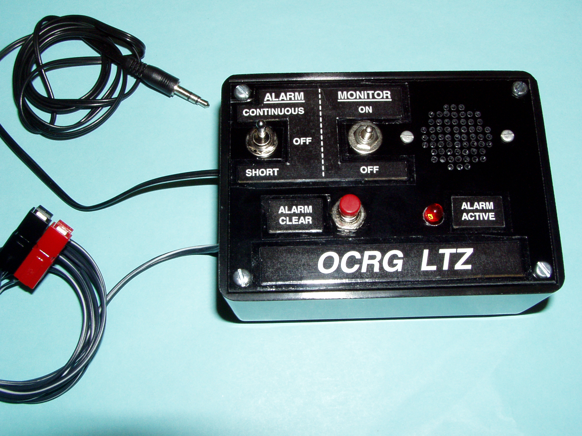
The LTZ is a Long Tone Zero Decoder. The LTZ provides several user selectable alert types to the user:
The monitor speaker may be manually turned on or off for monitoring of the source radio's audio signal whenever desired. The LTZ latches the decoded alert on, so even if one isn't present when the alert digit tone happens, the LTZ will still show an indication that an alert has previously occurred. The latched-on decoded alert is cleared with the momentary push-button "Alarm Clear" switch. By simply changing two resistors in the circuit, the LTZ can be modified to decode any other single digit of the Dual Tone Multi-Frequency available tone pairs. |
| LTZ_B01.zip |
|
Design files for the LTZ - Long Tone Zero Decoder. Includes schematics, PCB layout, and photos. |
|
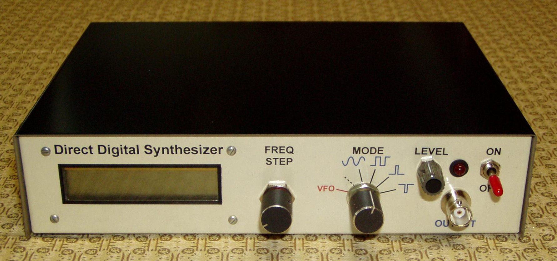
DigiVFO/DigiBrain Upgrade DigiVFO/DigiBrain Upgrade Document |
|
An upgrade for the DigiVFO/DigiBrain. This Direct Digital Synthesis VFO was initially described in the May 1995 and March 1996 QST magazine. This upgrade adds features and useful capabilities to the original design. The upgraded unit can easily be user set for compatibility with many different radios and/or used on the workbench as a signal generator. |
| DigiVFO_DigiBrain_Upgrade.zip |
Design files for the DigiVFO/DigiBrain upgrade. Includes schematics, micro-controller firmware source code, firmware hex image file, photos and mechanical details. Be sure to download the updated firmware below for the latest improvements! |
|
|
!!! Updated !!! |
This new firmware features a table driven method of looking up the frequency control bits. This results in much improved, and much higher speed, updating, allowing one to do super fast frequency dial twisting without overruns. The firmware source code also contains the previous improvement features of compiler switches to set "up" or "down" rotation of the step sequencing and the use of either the original Varitronics MDL-16265K-LV or the newer Lumex LCM-S01602DSF/A display (Digi-Key P/N 67-1758-ND) which uses the Samsung S6A0069 controller and also has an LED backlight. Also included are some improvements related to updating of the display when doing "mode changes" from VFO to Signal Generator and visa-versa. | |
|
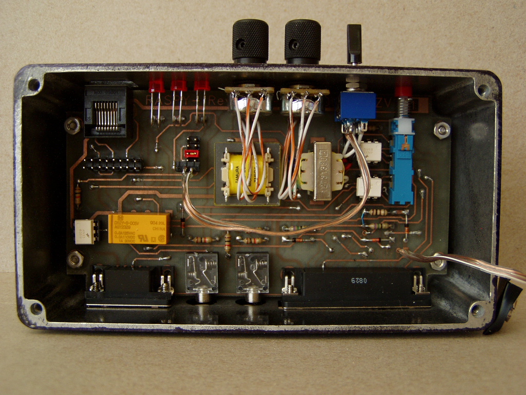
Dual Radio Sound Port Interface |
|
A dual radio interface to a PC sound port. |
| RASPY.zip |
Design files for the RASPY - Radio and Sound Port Yoke. Includes schematics, photos and mechanical details. |
|
|
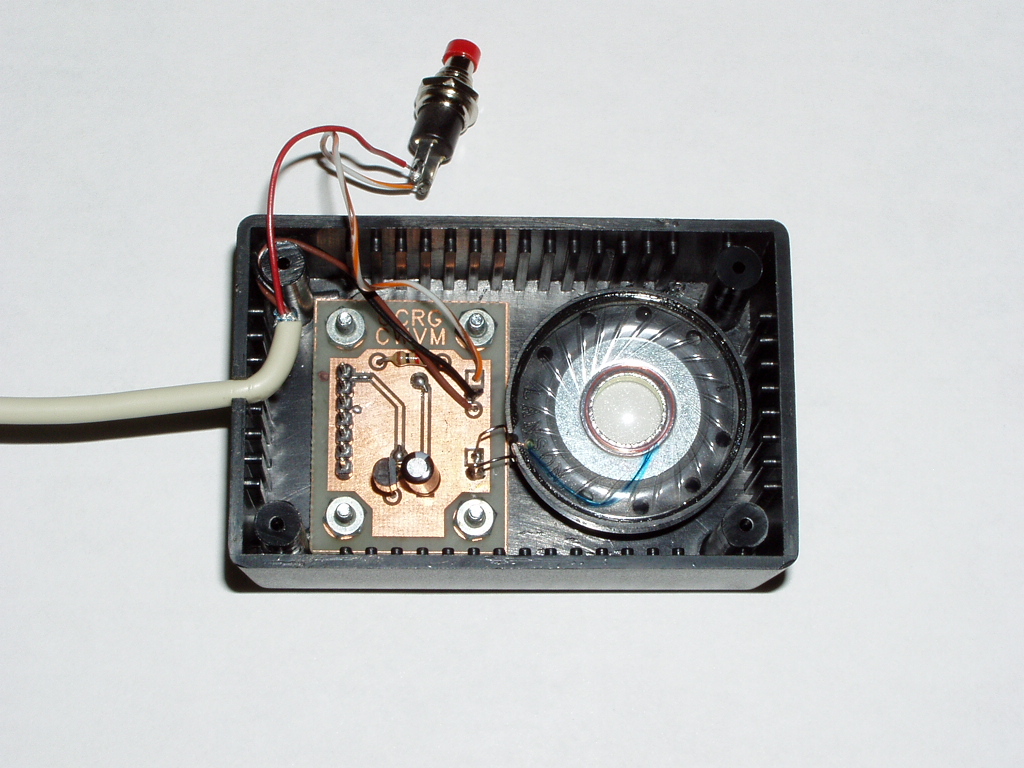
CW Voltmeter |
|
The CWVM is a low voltage, Morse code reporting, voltmeter. Instead of having to look at a display, the CWVM reports the reading in Morse code. The CW voltmeter operates from a +7VDC to +25VDC power source (9V battery or even the actual voltage source being monitored) and measures voltage levels from 0.00VDC to +25.50VDC. Pushing and holding the power button results in a Morse code voltage report similar to: "13.80V" followed by a two second delay. The report repeats, with a new A/D sample each time, as long as the button is pushed. Morse code sending speed is potentiometer adjustable from 5WPM to 45WPM. |
| CWVM.zip |
Design files for the CWVM - CW Voltmeter. Includes schematics, PCB layout, firmware source, hex image files, and photos. |
|
|
Repeater Audio Graphic Equalizer |
|
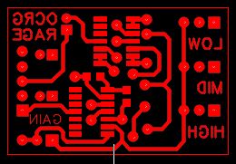
A Repeater Audio Graphic Equalizer small enough to fit inside almost any radio. This circuit provides individually adjustable audio levels in three different audio frequency bands to improve the readability of a radio's transmitted audio. |
| RAGE.zip |
Design files for the RAGE - Repeater Audio Graphic Equalizer. Includes schematics, PCB layout, and photos. |
|
Test Equipment |
||
|
The following links and files contain information for various test equipment. |
|
Impedance Meter - USB |
|
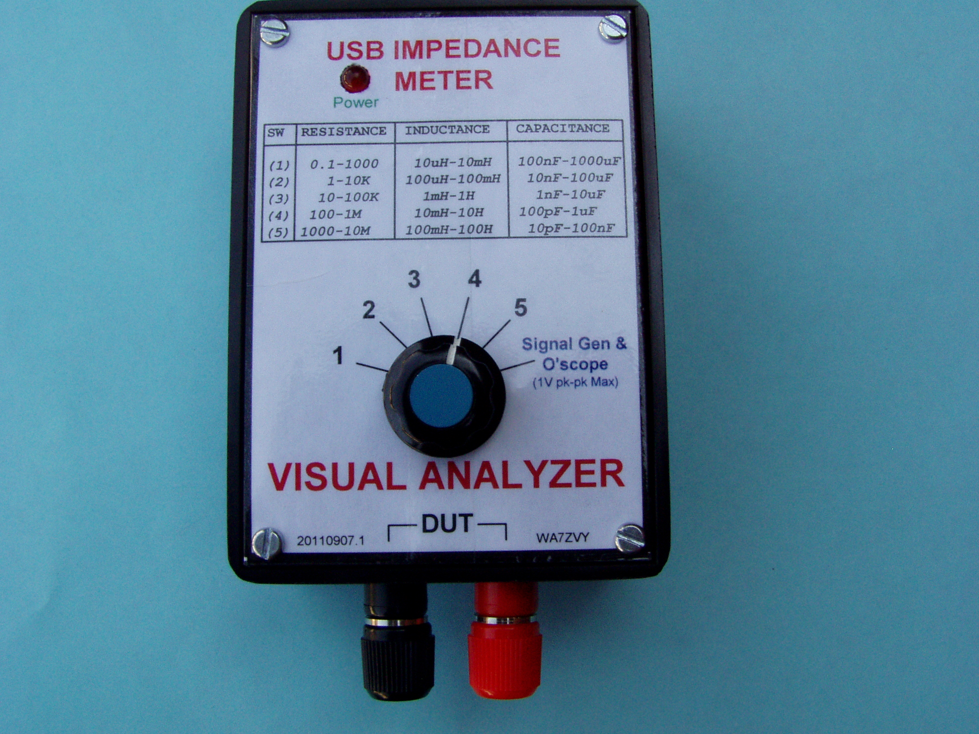
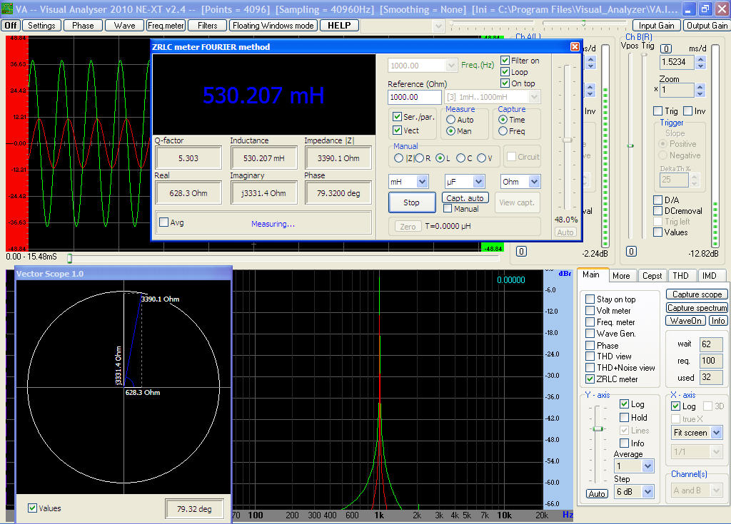
A surface mount implementation of Alfredo Accattatis' Visual Analyzer ZRLC Meter. This is one of the "coolest" pieces of test equipment that you could ever have. This relatively simple USB Sound Card Instrument is amazingly accurate and provides a wealth of information for those capacitors, inductors, resistors and other odds and ends in your parts bin or junk box. The Visual Analyzer software is free and is available from Alfredo Accattatis' excellent website: Visual Analyzer Software |
| VA_Zmeter_REV_A02.zip |
Design files for a surface mount implementation of the popular Visual Analyzer ZRLC Meter. Includes schematics, PCB layout, photos and details. |
|
|
Oscilloscope - USB |
|
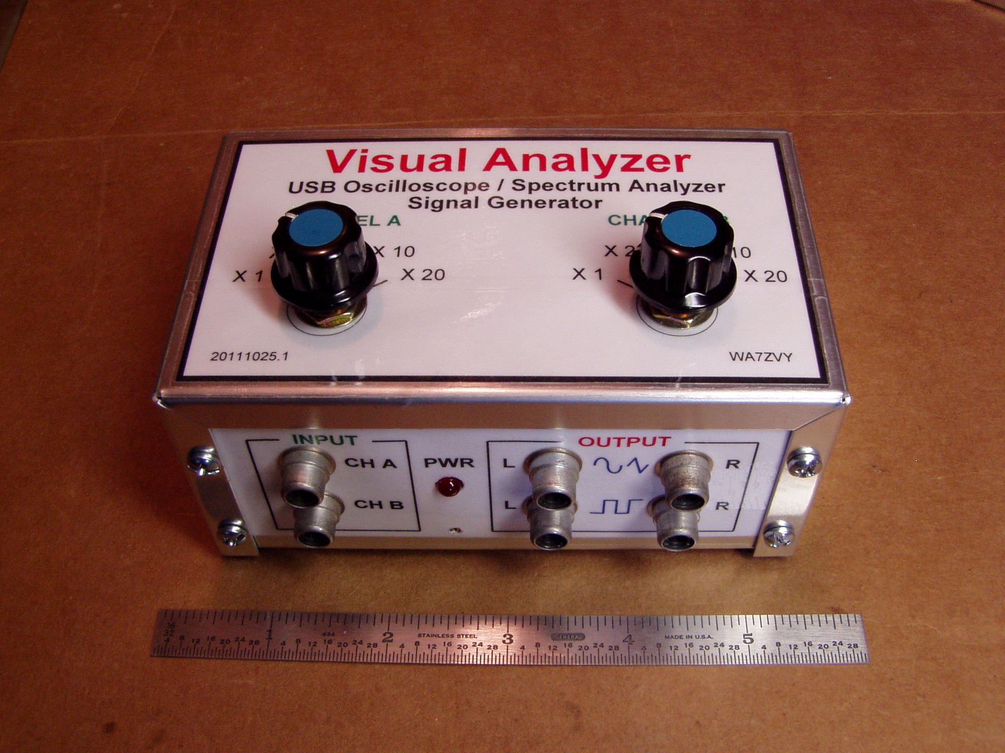
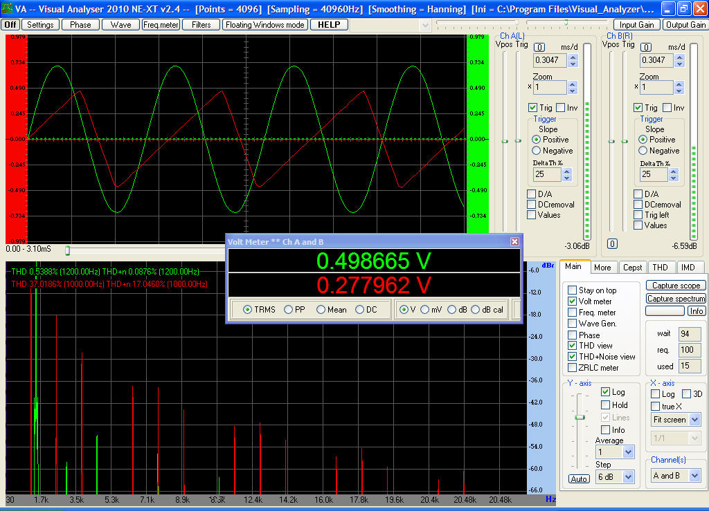
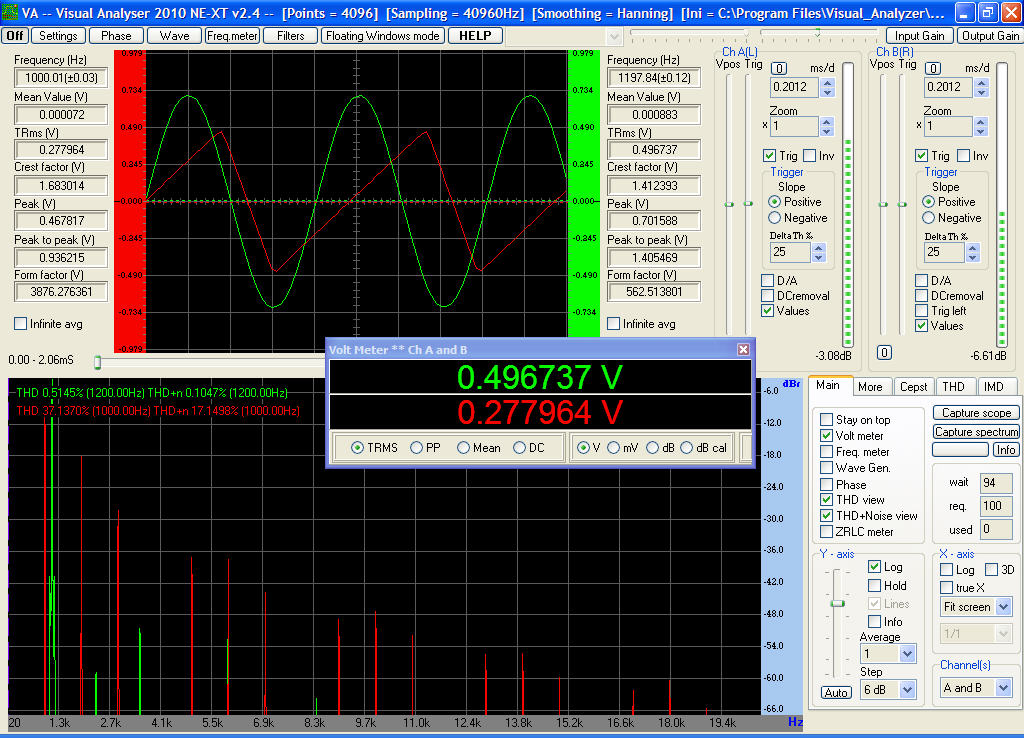
A surface mount implementation of the Visual Analyzer Oscilloscope/Spectrum Analyzer/Signal Generator. This is an audio frequency range piece of test equipment. While it only covers the audio frequency range (up to 48KHz; 96KHz sample rate), this instrument provides a wealth of information about the quality of audio signals. Along with being a dual channel oscilloscope, it also provides a dual channel spectrum analyzer and dual signal generators that are capable of producing a wide range of signals from sine waves, square waves, triangular waves, pulses, even custom waveforms, etc. Here is another screen shot of the Visual Analyzer in action. The Visual Analyzer software is free and available from Alfredo Accattatis' excellent website: Visual Analyzer Software |
| VA_Oscope_Rev_A01.zip |
Design files for a surface mount implementation of the popular Visual Analyzer Oscilloscope/Spectrum Analyzer/Signal Generator. Includes schematics, PCB layout, photos and details. |
|
|
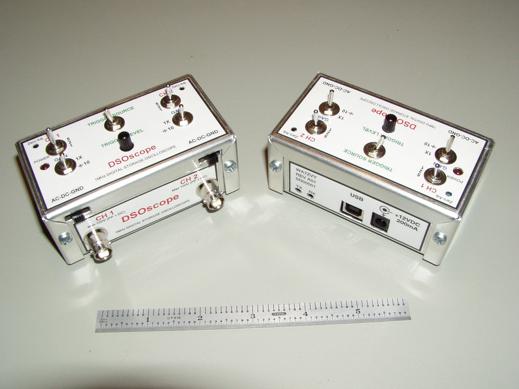
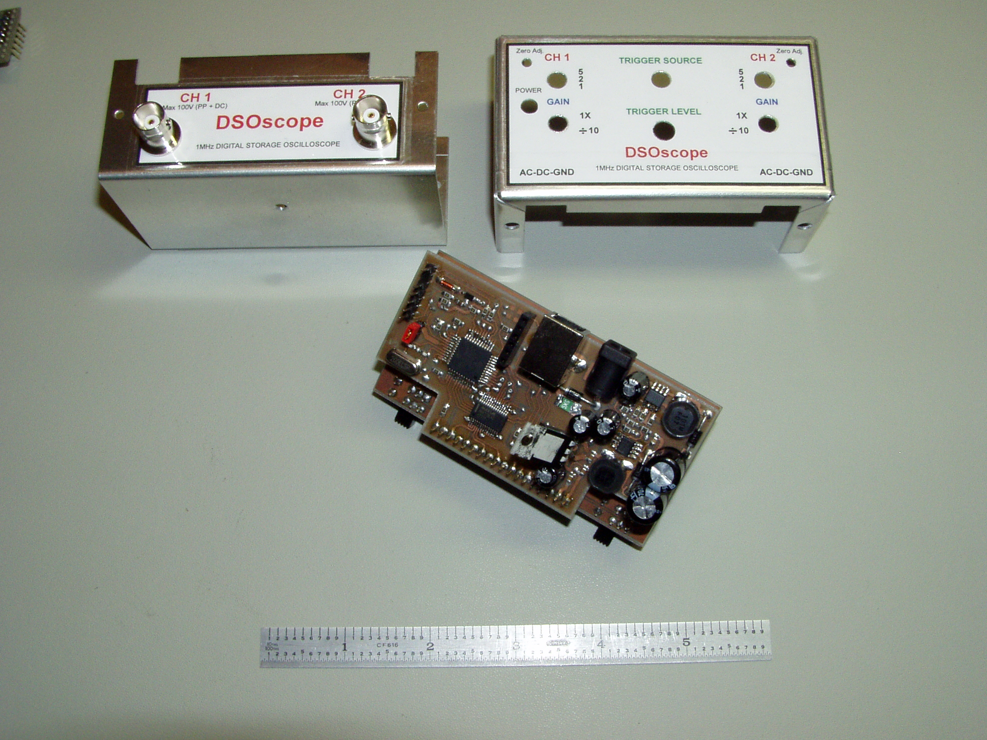
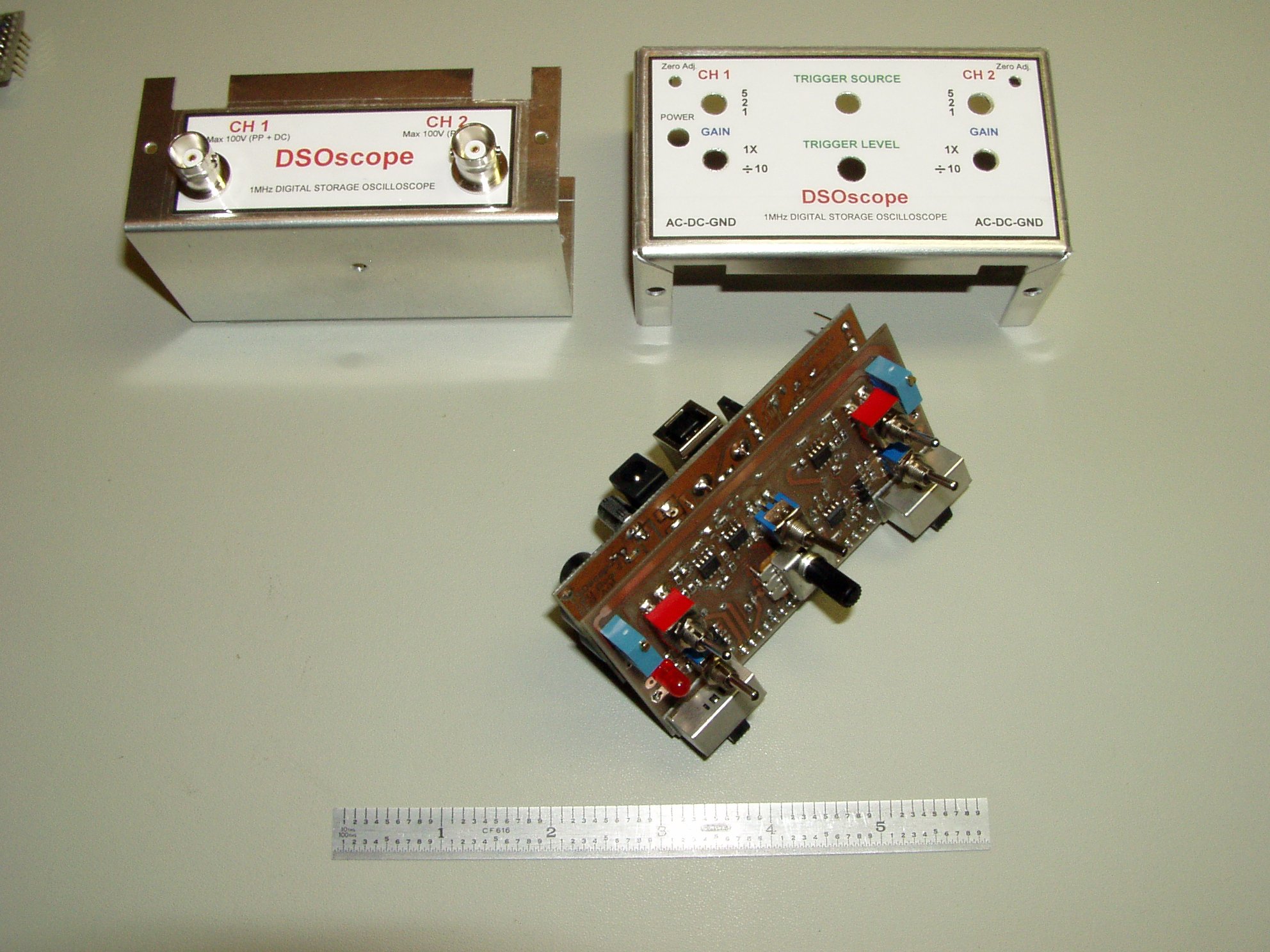
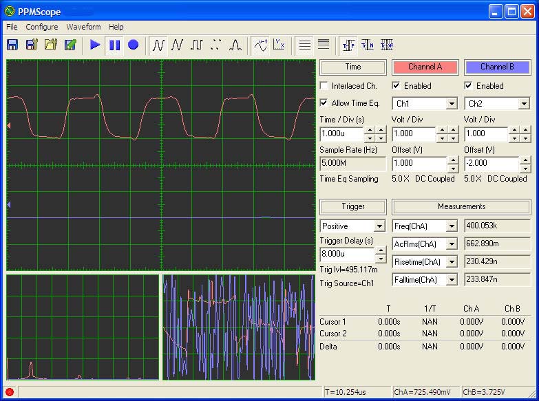
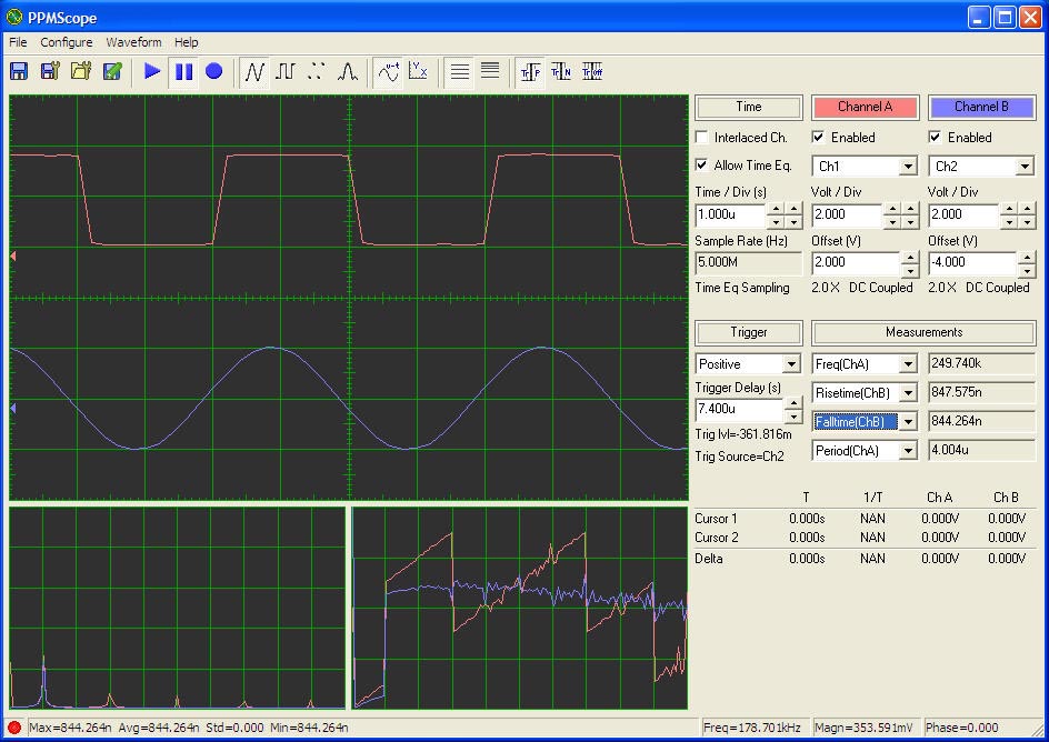
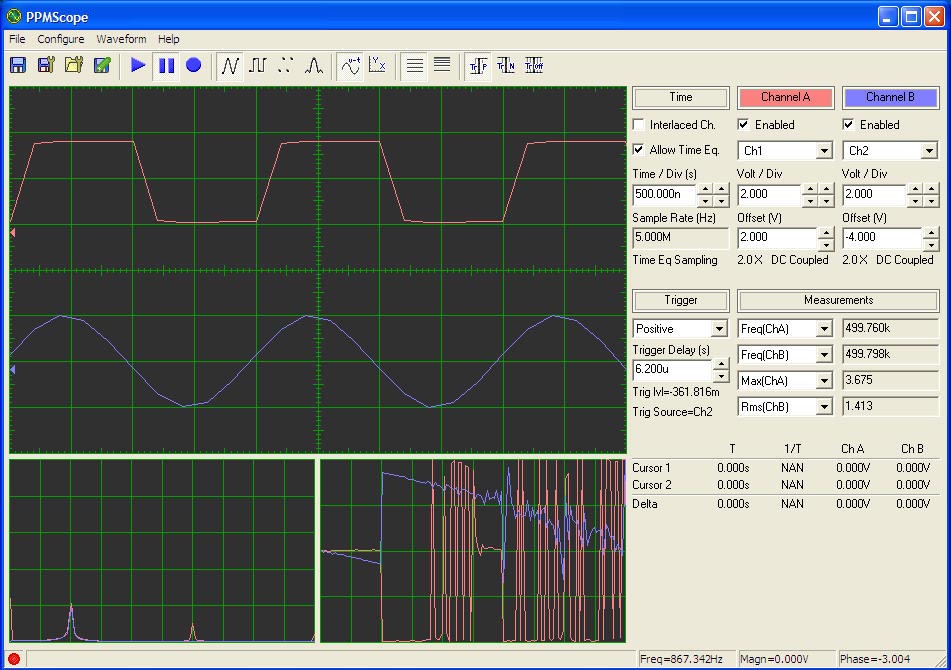
Digital Storage Oscilloscope
1MHz Dual Channel |
|
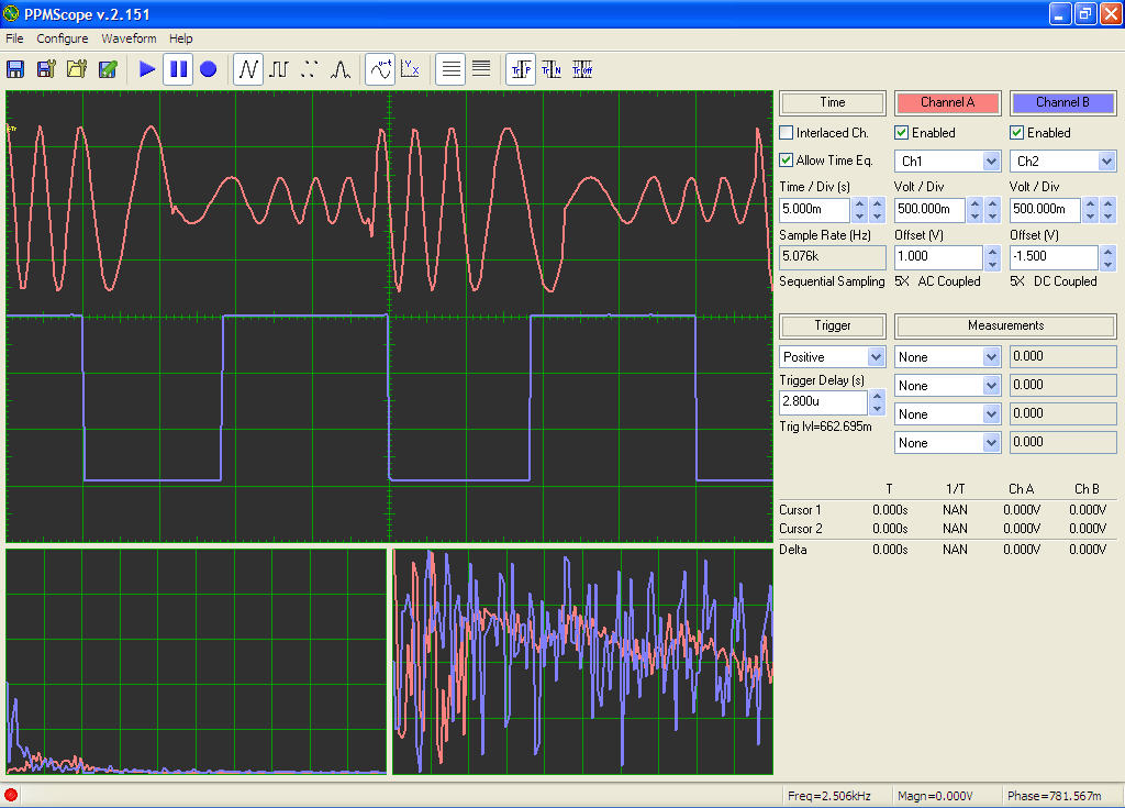
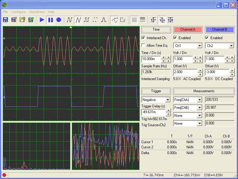
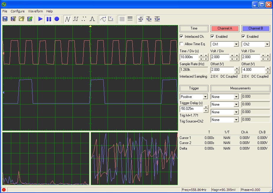
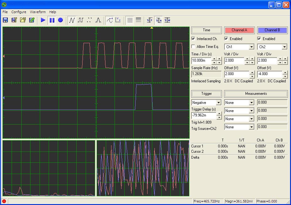
The DSOscope is a surface mount, and slightly modified/enhanced, implementation of Jonathan Weaver's famous PPMScope. The PPMScope is a 1.0 MHz sampling frequency, 5.0 MHz equivalent time, oscilloscope. Along with being a dual channel oscilloscope, the PPMscope also provides a spectrum analyzer function and multiple measurement capabilities for the displayed waveforms. The DSOscope version connects to the hosting PC via an internal USB interface. The internal USB interface uses the FT232RL serial to USB converter integrated circuit. The necessary driver code for the FT232RL is available from the FTDI website. The DSOscope is compatible with the PPMScope's PC software application code. Some of the feature enhancements of the DSOscope are:
A few screen captures of the DSOscope in action:
The PPMScope PC application software, that is compatible with, and used by the DSOscope implementation of the PPMscope, is available from Jonathan Weaver's PPMScope website. |
|
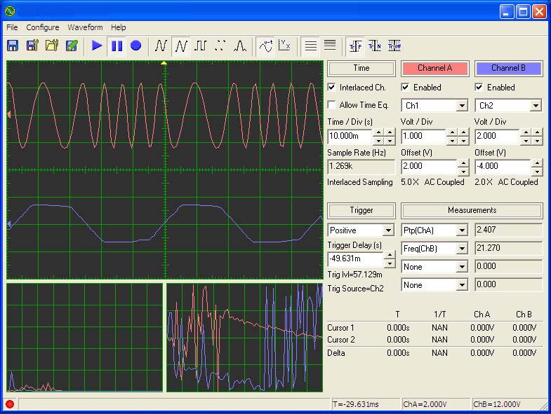
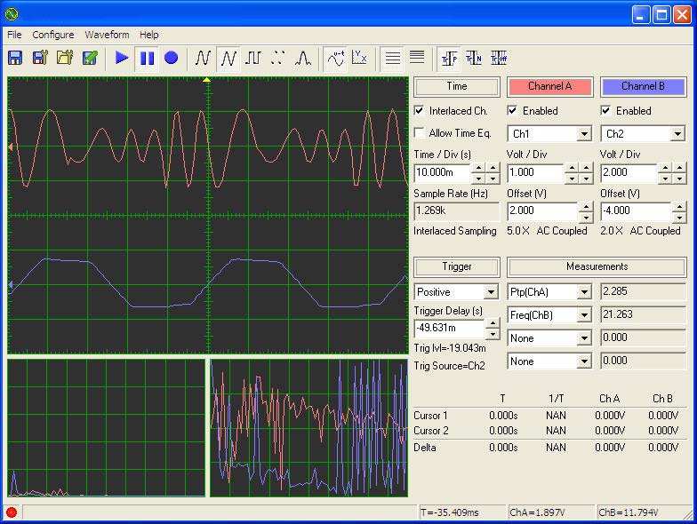
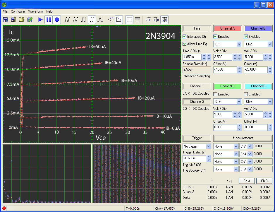
!!! New Version !!! !!! Important !!! |
Design files for the DSOscope version A03 (a surface mount, slightly modified version, of the PPMScope). The latest DSOscope firmware also includes a "pre-trigger" acquisition capability. While this "pre-trigger" capability is limited in its "pre-trigger" depth and works only for slower acquisition speeds, it can be quite useful when needing to look back in time from a trigger event. Some screen captures of the "pre-trigger" mode in action can be seen here: PreTrigger screen capture 1 and PreTrigger screen capture 2. (The yellow arrow at the top of the screen indicates the user setting of the trigger position, activated by using negative numbers in the "Trigger Delay (s)" box, while the "pre-trigger" captured waveforms preceed the yellow indicator arrow on the left with captured waveforms occurring after the trigger event being displayed to the right of the yellow indicator arrow.) The zip file includes: firmware, schematics, PCB layouts and mechanical drawings.
|
|
|
Library symbol files used with the FreePCB and the TinyCAD design tools for the DSOscope. |
||
|
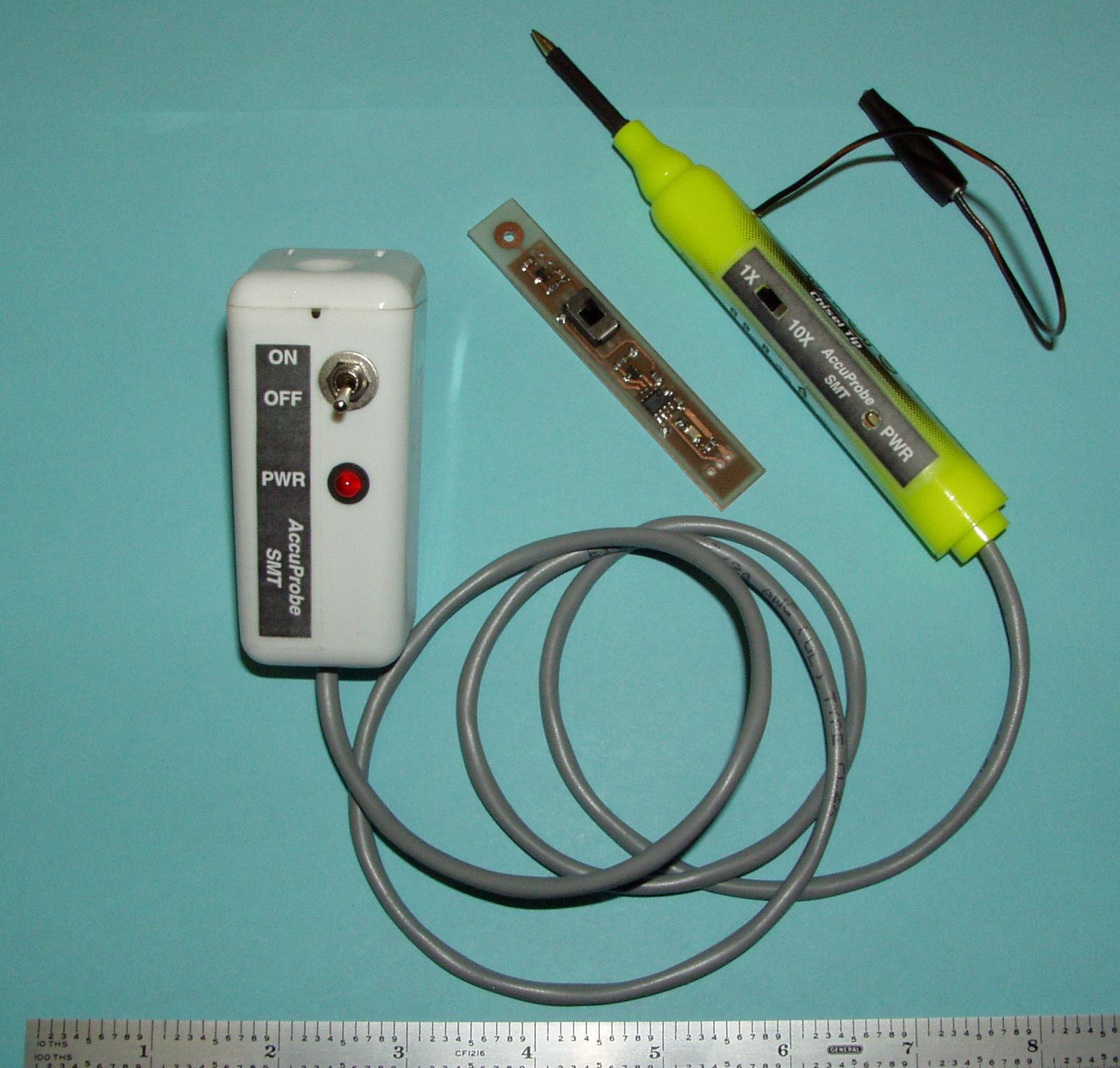
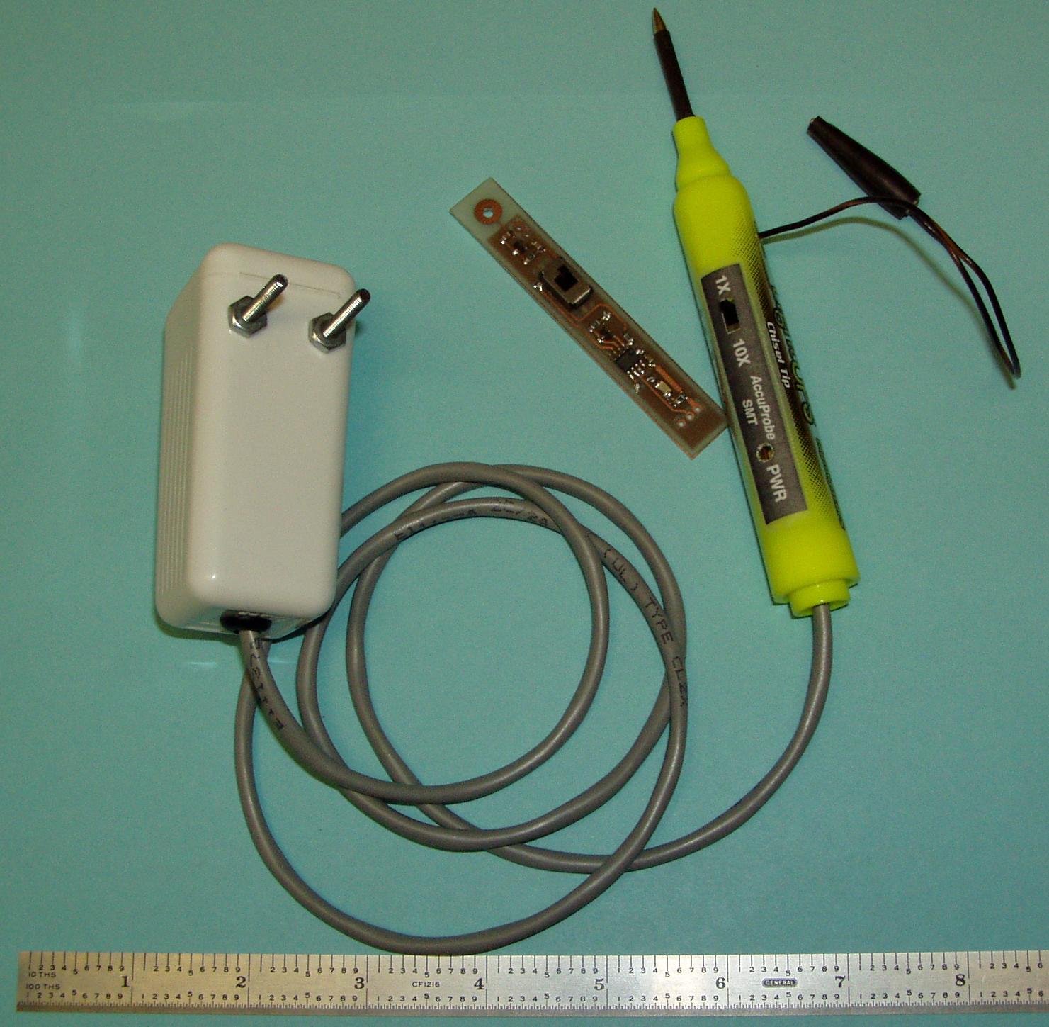
Accuprobe SMT RF Amplitude Measurement Probe |
|
The "Accuprobe SMT" is a surface mount implementation of the N2CX Accuprobe
RF Detector Probe. The smaller size allows the actual probe circuitry
to fit inside a highlighter pen barrel. Thus making the probe easier
to handle and hold, especially in tight areas. |
| Accuprobe_SMT.zip |
Design files for the "Accuprobe SMT" RF Detector Probe. Includes schematics, PCB layout, photos and details. |
|
Workbench - Techniques and Methods |
|
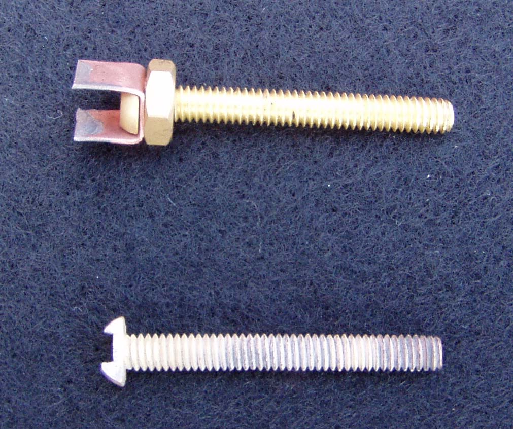
SMT Desoldering Tips |
|
The photo on the left shows two SMT Desoldering Tips that have been made from 1.375 inch long by 8-32 pan head brass bolts. The SMT Desoldering Tip, shown at the top of the photo on the left, is used to unsolder SOIC-8 pin devices. It was created by filing the pan head slightly narrower and then adding a small U-shape bent piece of copper sheet stock that has a 5/32" hole drilled in the center of it. The U-shaped copper is attached with an 8-32 brass hex nut. Using this same technique, desoldering tips can be built for various SOIC sized devices. By adding a second piece of copper sheet stock, rotated by 90 degrees, it is possible to build desoldering tips for TQFP style devices. The SMT Desoldering Tip, shown at the bottom of the photo on the left, is used to unsolder 0805 SMT devices. It was created by filing a notch into the pan head of the brass bolt along with filing the pan head a bit narrower. Again, using this same notch filing technique, desoldering tips can be built for various size SMT devices such as 1210, 0805, 0603, and even the smaller 0402 devices. The SMT Desoldering Tip is installed, in place of a standard replaceable 5/32" soldering iron tip, in a cheap 25 watt soldering iron that uses plain, solid metal, soldering iron tips. When used, it is handy to have a small pair of tweezers, or a toothpick handy, to quickly remove the unsoldered device from the SMT Desoldering Tip as the desoldered device will likely "stick" to the desoldering tip as it is removed from the printed circuit board. Also, very lightly pre-tinning the SMT Desoldering Tip helps transfer heat to the to be removed device's pins. |
|
OCRG has been using circuit board fabrication products from "Pulsar" to produce many of our system unique circuit boards. These circuit boards range from simple one-sided attenuator boards for our A/D conversion telemetry to two layer fine pitch SMT boards with dual CPUs for processing our weather station data. Pulsar's website contains excellent information on fabricating PCBs using The "DirectEtch" Technique with their complete PCB "Fab-in-a-Box" products. | |
|
|
Technology and techniques for making printed circuit boards using a laser printer toner transfer methodology. |
|
|
|
